The good, the bad and the ugly: Design and construction for access (2008)
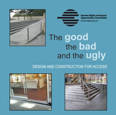
The good, the bad and the ugly:
Design and construction for access
New partnership with Councils
Disability Discrimination Commissioner Graeme Innes has announced a partnership project between the Australian Human Rights Commission and Marrickville Council in NSW designed to improve access to buildings in the council area for people with a disability.
The project involves provision of a free CD, entitled The good, the bad and the ugly, to every person who makes a relevant application to Marrickville Council for an approval to construct or renovate a commercial building.
Developed by the Australian Human Rights Commission for designers, builders and owners, the CD explains why it is so important to accurately comply with the technical specifications for access.
The CD also includes a letter from Commissioner Innes and the Mayor of Marrickville Council, Councillor Iskandar, that explains the importance of providing good access and will be made available to all applicants by the Council's Development Assessment section.
Marrickville Council have also sent copies of the CD to all schools in the area who may have access to building project grant funds and to active developers who regularly make applications to Council.
Commissioner Innes is encouraging other Councils throughout Australia to follow this example and contact Michael Small at the Commission to find out more about the partnership. Michael.small@humanrights.gov.au
Welcome to this collection of resources aimed at providing information and guidance to designers, builders, planners, certifiers, building managers and access consultants about access to buildings and services for people with disabilities.
There are two resources in this collection, which can also be obtained on CD free of charge on request to publications@humanrights.gov.au:
- The good, the bad and the ugly (Word) or HTML version. A look at 14 examples of the most common problems and misinterpretations in applying today's Building Code of Australia (BCA) in the area of access. The good, the bad and the ugly shows in words and pictures why a thorough understanding and application of the BCA is vital to ensuring access.
The good, the bad and the ugly can be used as a self learning tool or used as part of a continuing education program, for example, in a Local Government Building Section or within an architects firm.
- Guidelines on access to buildings and services (Word) or HTML version. The guidelines are aimed at businesses, service providers, Government agencies, property managers and anyone involved in the purchasing, leasing or assessment of property. The aim of the guideline is to assist in identifying possible barriers to buildings and services and direct people to resources and expertise to address those barriers.
This is the second edition of these resources. Comments from those who received the earlier edition include:
"I have just read through your most informative material on The Good the bad and the ugly. There should be more like this on all significant issues to do with the building. Simple to follow, informative and with enough information to send the reader to the BCA!" (Building Consultants in WA)
"Thanks for sending me this. The day I got it I happened to be working on something that was covered in the examples and used it twice to make sure I was on the right track." (Architect NSW)
"Just a quick note of thanks for this paper. It puts flesh and blood meaning into an anonymous Code which all too often is seen by building designers as more bureaucratic red tape to be hurdled before gaining approval, rather than a positive guide to assisting access and mobility." (Architect Qld)
I hope these resources are useful to you and help in improving the accessibility of the built environment.

Graeme Innes AM
Human Rights Commissioner &
Disability Discrimination Commissioner
April 2008
Acknowledgements
This material has been produced by the Australian Human Rights Commission (the Commission) and may be used, reproduced and distributed so long as the source is acknowledged.
The Commission acknowledges the work of Murray Mountain in the preparation of The good, the bad and the ugly and the photographs used in that resource and the assistance of Mark Relf in preparing this edition. The Commission also thanks the many people who commented on early drafts of both documents.